Architecture
Cluster and Primary Logic Unit
The design of TDengine is based on the assumption that any hardware or software system is not 100% reliable and that no single node can provide sufficient computing and storage resources to process massive data. Therefore, since day one, TDengine has been designed as a natively distributed system, with high-reliability architecture. Hardware failure or software failure of a single, or even multiple servers will not affect the availability and reliability of the system. At the same time, through node virtualization and automatic load-balancing technology, TDengine can make the most efficient use of computing and storage resources in heterogeneous clusters to reduce hardware resource needs, significantly.
Primary Logic Unit
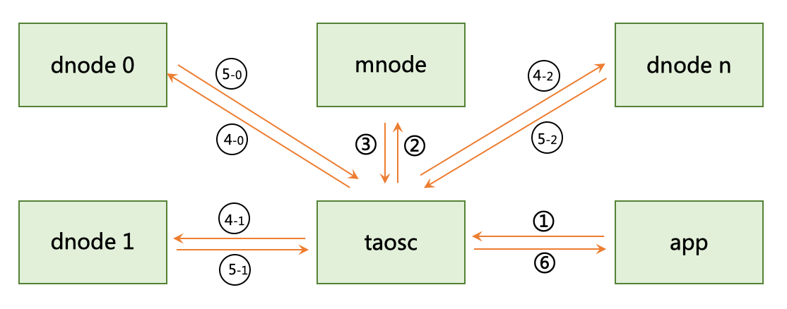
Logical structure diagram of TDengine's distributed architecture is as follows:
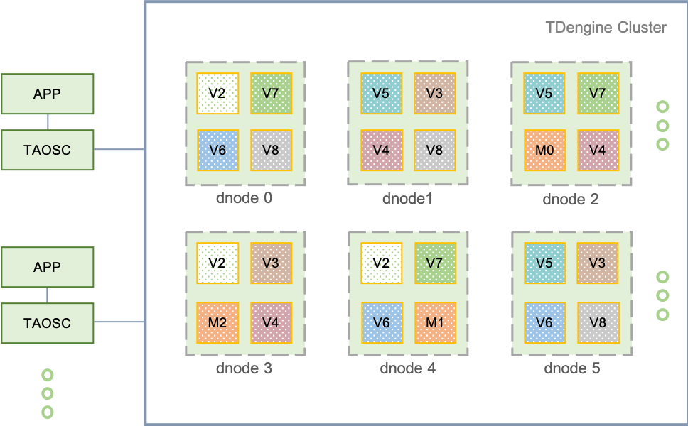
A complete TDengine system runs on one or more physical nodes. Logically, it includes data node (dnode), TDengine client driver (TAOSC) and application (app). There are one or more data nodes in the system, which form a cluster. The application interacts with the TDengine cluster through TAOSC's API. The following is a brief introduction to each logical unit.
Physical node (pnode): A pnode is a computer that runs independently and has its own computing, storage and network capabilities. It can be a physical machine, virtual machine, or Docker container installed with OS. The physical node is identified by its configured FQDN (Fully Qualified Domain Name). TDengine relies entirely on FQDN for network communication. If you don't know about FQDN, please check wikipedia.
Data node (dnode): A dnode is a running instance of the TDengine server-side execution code taosd on a physical node (pnode). A working system must have at least one data node. A dnode contains zero to multiple logical virtual nodes (VNODE) and zero or at most one logical management node (mnode). The unique identification of a dnode in the system is determined by the instance's End Point (EP). EP is a combination of FQDN (Fully Qualified Domain Name) of the physical node where the dnode is located and the network port number (Port) configured by the system. By configuring different ports, a physical node (a physical machine, virtual machine or container) can run multiple instances or have multiple data nodes.
Virtual node (vnode): To better support data sharding, load balancing and prevent data from overheating or skewing, data nodes are virtualized into multiple virtual nodes (vnode, V2, V3, V4, etc. in the figure). Each vnode is a relatively independent work unit, which is the basic unit of time-series data storage and has independent running threads, memory space and persistent storage path. A vnode contains a certain number of tables (data collection points). When a new table is created, the system checks whether a new vnode needs to be created. The number of vnodes that can be created on a data node depends on the capacity of the hardware of the physical node where the data node is located. A vnode belongs to only one DB, but a DB can have multiple vnodes. In addition to the stored time-series data, a vnode also stores the schema and tag values of the included tables. A virtual node is uniquely identified in the system by the EP of the data node and the VGroup ID to which it belongs and is created and managed by the management node.
Management node (mnode): A virtual logical unit responsible for monitoring and maintaining the running status of all data nodes and load balancing among nodes (M in the figure). At the same time, the management node is also responsible for the storage and management of metadata (including users, databases, tables, static tags, etc.), so it is also called Meta Node. Multiple (up to 3) mnodes can be configured in a TDengine cluster, and they are automatically constructed into a virtual management node group (M0, M1, M2 in the figure). The leader/follower mechanism is adopted for the mnode group and the data synchronization is carried out in a strongly consistent way. Any data update operation can only be executed on the leader. The creation of mnode cluster is completed automatically by the system without manual intervention. There is at most one mnode on each dnode, which is uniquely identified by the EP of the data node to which it belongs. Each dnode automatically obtains the EP of the dnode where all mnodes in the whole cluster are located, through internal messaging interaction.
Virtual node group (VGroup): Vnodes on different data nodes can form a virtual node group to ensure the high availability of the system. The virtual node group is managed in a leader/follower mechanism. Write operations can only be performed on the leader vnode, and then replicated to follower vnodes, thus ensuring that one single replica of data is copied on multiple physical nodes. The number of virtual nodes in a vgroup equals the number of data replicas. If the number of replicas of a DB is N, the system must have at least N data nodes. The number of replicas can be specified by the parameter “replica” when creating a DB, and the default is 1. Using the multi-replication feature of TDengine, the same high data reliability can be achieved without the need for expensive storage devices such as disk arrays. Virtual node groups are created and managed by the management node, and the management node assigns a system unique ID, aka VGroup ID. If two virtual nodes have the same vnode group ID, it means that they belong to the same group and the data is backed up to each other. The number of virtual nodes in a virtual node group can be dynamically changed, allowing only one, that is, no data replication. VGroup ID is never changed. Even if a virtual node group is deleted, its ID will not be reused.
TAOSC: TAOSC is the driver provided by TDengine to applications. It is responsible for dealing with the interaction between application and cluster, and provides the native interface for the C/C++ language. It is also embedded in the JDBC, C #, Python, Go, Node.js language connection libraries. Applications interact with the whole cluster through TAOSC instead of directly connecting to data nodes in the cluster. This module is responsible for obtaining and caching metadata; forwarding requests for insertion, query, etc. to the correct data node; when returning the results to the application, TAOSC also needs to be responsible for the final level of aggregation, sorting, filtering and other operations. For JDBC, C/C++/C#/Python/Go/Node.js interfaces, this module runs on the physical node where the application is located. At the same time, in order to support the fully distributed RESTful interface, TAOSC has a running instance on each dnode of TDengine cluster.
Node Communication
Communication mode: The communication among each data node of TDengine system, and among the client driver and each data node is carried out through TCP/UDP. Considering an IoT scenario, the data writing packets are generally not large, so TDengine uses UDP in addition to TCP for transmission, because UDP is more efficient and is not limited by the number of connections. TDengine implements its own timeout, retransmission, confirmation and other mechanisms to ensure reliable transmission of UDP. For packets with a data volume of less than 15K, UDP is adopted for transmission, and TCP is automatically adopted for transmission of packets with a data volume of more than 15K or query operations. At the same time, TDengine will automatically compress/decompress the data, digitally sign/authenticate the data according to the configuration and data packet. For data replication among data nodes, only TCP is used for data transportation.
FQDN configuration: A data node has one or more FQDNs, which can be specified in the system configuration file taos.cfg with the parameter “fqdn”. If it is not specified, the system will automatically use the hostname of the computer as its FQDN. If the node is not configured with FQDN, you can directly set the configuration parameter “fqdn” of the node to its IP address. However, IP is not recommended because IP address may be changed, and once it changes, the cluster will not work properly. The EP (End Point) of a data node consists of FQDN + Port. With FQDN, it is necessary to ensure the DNS service is running, or hosts files on nodes are configured properly.
Port configuration: The external port of a data node is determined by the system configuration parameter “serverPort” in TDengine, and the port for internal communication of cluster is serverPort+5. The data replication operation among data nodes in the cluster also occupies a TCP port, which is serverPort+10. In order to support multithreading and efficient processing of UDP data, each internal and external UDP connection needs to occupy 5 consecutive ports. Therefore, the total port range of a data node will be serverPort to serverPort + 10, for a total of 11 TCP/UDP ports. To run the system, make sure that the firewall keeps these ports open. Each data node can be configured with a different serverPort.
Cluster external connection: TDengine cluster can accommodate a single, multiple or even thousands of data nodes. The application only needs to initiate a connection to any data node in the cluster. The network parameter required for connection is the End Point (FQDN plus configured port number) of a data node. When starting the application taos through CLI, the FQDN of the data node can be specified through the option -h, and the configured port number can be specified through -p. If the port is not configured, the system configuration parameter “serverPort” of TDengine will be adopted.
Inter-cluster communication: Data nodes connect with each other through TCP/UDP. When a data node starts, it will obtain the EP information of the dnode where the mnode is located, and then establish a connection with the mnode in the system to exchange information. There are three steps to obtain EP information of the mnode:
- Check whether the mnodeEpList file exists, if it does not exist or cannot be opened normally to obtain EP information of the mnode, skip to the second step;
- Check the system configuration file taos.cfg to obtain node configuration parameters “firstEp” and “secondEp” (the node specified by these two parameters can be a normal node without mnode, in this case, the node will try to redirect to the mnode node when connected). If these two configuration parameters do not exist or do not exist in taos.cfg, or are invalid, skip to the third step;
- Set your own EP as a mnode EP and run it independently. After obtaining the mnode EP list, the data node initiates the connection. It will successfully join the working cluster after connection. If not successful, it will try the next item in the mnode EP list. If all attempts are made, but the connection still fails, sleep for a few seconds before trying again.
The choice of MNODE: TDengine logically has a management node, but there is no separate execution code. The server-side only has one set of execution code, taosd. So which data node will be the management node? This is determined automatically by the system without any manual intervention. The principle is as follows: when a data node starts, it will check its End Point and compare it with the obtained mnode EP List. If its EP exists in it, the data node shall start the mnode module and become a mnode. If your own EP is not in the mnode EP List, the mnode module will not start. During the system operation, due to load balancing, downtime and other reasons, mnode may migrate to the new dnode, totally transparently and without manual intervention. The modification of configuration parameters is the decision made by mnode itself according to resources usage.
Add new data nodes: After the system has a data node, it has become a working system. There are two steps to add a new node into the cluster.
- Step1: Connect to the existing working data node using TDengine CLI, and then add the End Point of the new data node with the command "create dnode"
- Step 2: In the system configuration parameter file taos.cfg of the new data node, set the “firstEp” and “secondEp” parameters to the EP of any two data nodes in the existing cluster. Please refer to the user tutorial for detailed steps. In this way, the cluster will be established step by step.
Redirection: Regardless of dnode or TAOSC, the connection to the mnode is initiated first. The mnode is automatically created and maintained by the system, so the user does not know which dnode is running the mnode. TDengine only requires a connection to any working dnode in the system. Because any running dnode maintains the currently running mnode EP List, when receiving a connecting request from the newly started dnode or TAOSC, if it’s not an mnode itself, it will reply to the mnode with the EP List. After receiving this list, TAOSC or the newly started dnode will try to establish the connection again. When the mnode EP List changes, each data node quickly obtains the latest list and notifies TAOSC through messaging interaction among nodes.
A Typical Data Writing Process
To explain the relationship between vnode, mnode, TAOSC and application and their respective roles, the following is an analysis of a typical data writing process.
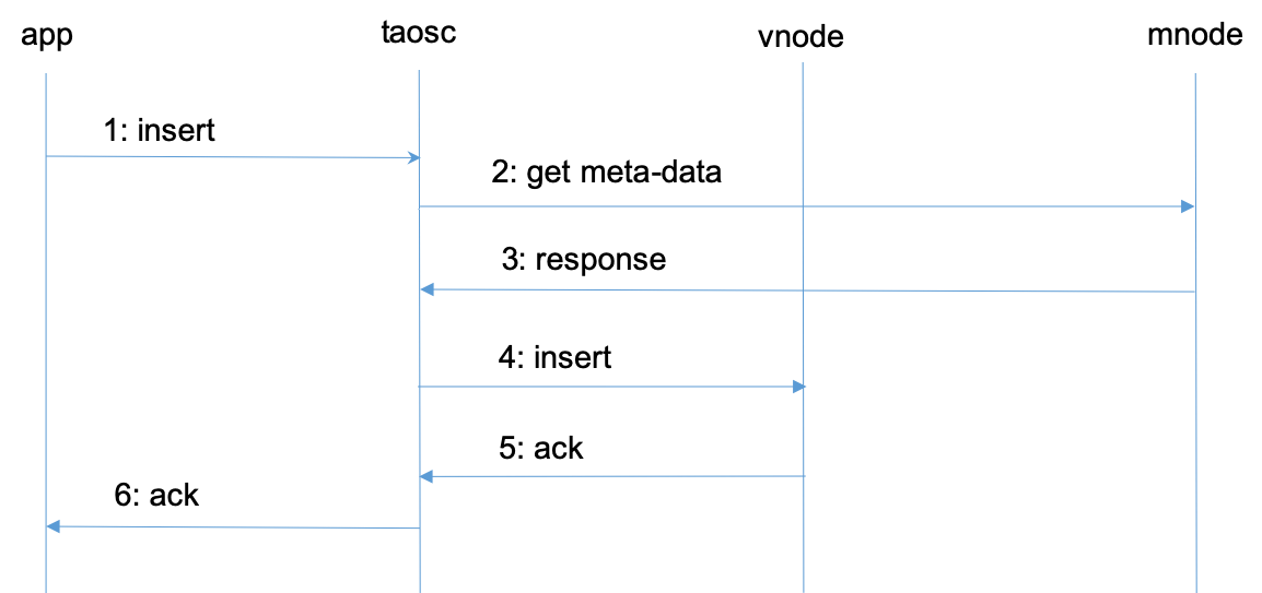
- Application initiates a request to insert data through JDBC, ODBC, or other APIs.
- TAOSC checks the cache to see if meta data exists for the table. If it does, it goes straight to Step 4. If not, TAOSC sends a get meta-data request to mnode.
- Mnode returns the meta-data of the table to TAOSC. Meta-data contains the schema of the table, and also the vgroup information to which the table belongs (the vnode ID and the End Point of the dnode where the table belongs. If the number of replicas is N, there will be N groups of End Points). If TAOSC does not receive a response from the mnode for a long time, and there are multiple mnodes, TAOSC will send a request to the next mnode.
- TAOSC initiates an insert request to leader vnode.
- After vnode inserts the data, it gives a reply to TAOSC, indicating that the insertion is successful. If TAOSC doesn't get a response from vnode for a long time, TAOSC will treat this node as offline. In this case, if there are multiple replicas of the inserted database, TAOSC will issue an insert request to the next vnode in vgroup.
- TAOSC notifies APP that writing is successful.
For Step 2 and 3, when TAOSC starts, it does not know the End Point of mnode, so it will directly initiate a request to the configured serving End Point of the cluster. If the dnode that receives the request does not have a mnode configured, it will reply with the mnode EP list, so that TAOSC will re-issue a request to obtain meta-data to the EP of another mnode.
For Step 4 and 5, without caching, TAOSC can't recognize the leader in the virtual node group, so assumes that the first vnode is the leader and sends a request to it. If this vnode is not the leader, it will reply to the actual leader as a new target to which TAOSC shall send a request. Once a response of successful insertion is obtained, TAOSC will cache the information of leader node.
The above describes the process of inserting data. The processes of querying and computing are the same. TAOSC encapsulates and hides all these complicated processes, and it is transparent to applications.
Through TAOSC caching mechanism, mnode needs to be accessed only when a table is accessed for the first time, so mnode will not become a system bottleneck. However, because schema and vgroup may change (such as load balancing), TAOSC will interact with mnode regularly to automatically update the cache.
Storage Model and Data Partitioning/Sharding
Storage Model
The data stored by TDengine includes collected time-series data, metadata related to database and tables, tag data, etc. All of the data is specifically divided into three parts:
- Time-series data: stored in vnode and composed of data, head and last files. The amount of data is large and query amount depends on the application scenario. Out-of-order writing is allowed, but delete operation is not supported for the time being, and update operation is only allowed when database “update” parameter is set to 1. By adopting the model with one table for each data collection point, the data of a given time period is continuously stored, and the writing against one single table is a simple appending operation. Multiple records can be read at one time, thus ensuring the best performance for both insert and query operations of a single data collection point.
- Tag data: meta files stored in vnode. Four standard operations of create, read, update and delete are supported. The amount of data is not large. If there are N tables, there are N records, so all can be stored in memory. To make tag filtering efficient, TDengine supports multi-core and multi-threaded concurrent queries. As long as the computing resources are sufficient, even with millions of tables, the tag filtering results will return in milliseconds.
- Metadata: stored in mnode and includes system node, user, DB, table schema and other information. Four standard operations of create, delete, update and read are supported. The amount of this data is not large and can be stored in memory. Moreover, the number of queries is not large because of client cache. Even though TDengine uses centralized storage management, because of the architecture, there is no performance bottleneck.
Compared with the typical NoSQL storage model, TDengine stores tag data and time-series data completely separately. This has two major advantages:
- Reduces the redundancy of tag data storage significantly. General NoSQL database or time-series database adopts K-V (key-value) storage, in which the key includes a timestamp, a device ID and various tags. Each record carries these duplicated tags, so storage space is wasted. Moreover, if the application needs to add, modify or delete tags on historical data, it has to traverse the data and rewrite them again, which is an extremely expensive operation.
- Aggregate data efficiently between multiple tables: when aggregating data between multiple tables, it first finds the tables which satisfy the filtering conditions, and then finds the corresponding data blocks of these tables. This greatly reduces the data sets to be scanned which in turn improves the aggregation efficiency. Moreover, tag data is managed and maintained in a full-memory structure, and tag data queries in tens of millions can return in milliseconds.
Data Sharding
For large-scale data management, to achieve scale-out, it is generally necessary to adopt a Partitioning or Sharding strategy. TDengine implements data sharding via vnode, and time-series data partitioning via one data file for a time range.
VNode (Virtual Data Node) is responsible for providing writing, query and computing functions for collected time-series data. To facilitate load balancing, data recovery and support heterogeneous environments, TDengine splits a data node into multiple vnodes according to its computing and storage resources. The management of these vnodes is done automatically by TDengine and is completely transparent to the application.
For a single data collection point, regardless of the amount of data, a vnode (or vnode group, if the number of replicas is greater than 1) has enough computing resource and storage resource to process (if a 16-byte record is generated per second, the original data generated in one year will be less than 0.5 G). So TDengine stores all the data of a table (a data collection point) in one vnode instead of distributing the data to two or more dnodes. Moreover, a vnode can store data from multiple data collection points (tables), and the upper limit of the tables’ quantity for a vnode is one million. By design, all tables in a vnode belong to the same DB. On a data node, unless specially configured, the number of vnodes owned by a DB will not exceed the number of system cores.
When creating a DB, the system does not allocate resources immediately. However, when creating a table, the system will check if there is an allocated vnode with free tablespace. If so, the table will be created in the vacant vnode immediately. If not, the system will create a new vnode on a dnode from the cluster according to the current workload, and then a table. If there are multiple replicas of a DB, the system does not create only one vnode, but a vgroup (virtual data node group). The system has no limit on the number of vnodes, which is just limited by the computing and storage resources of physical nodes.
The meta data of each table (including schema, tags, etc.) is also stored in vnode instead of centralized storage in mnode. In fact, this means sharding of meta data, which is good for efficient and parallel tag filtering operations.
Data Partitioning
In addition to vnode sharding, TDengine partitions the time-series data by time range. Each data file contains only one time range of time-series data, and the length of the time range is determined by the database configuration parameter “days”. This method of partitioning by time range is also convenient to efficiently implement data retention policies. As long as the data file exceeds the specified number of days (system configuration parameter “keep”), it will be automatically deleted. Moreover, different time ranges can be stored in different paths and storage media, so as to facilitate tiered-storage. Cold/hot data can be stored in different storage media to significantly reduce storage costs.
In general, TDengine splits big data by vnode and time range in two dimensions to manage the data efficiently with horizontal scalability.
Load Balancing
Each dnode regularly reports its status (including hard disk space, memory size, CPU, network, number of virtual nodes, etc.) to the mnode (virtual management node) so that the mnode knows the status of the entire cluster. Based on the overall status, when the mnode finds a dnode is overloaded, it will migrate one or more vnodes to other dnodes. During the process, TDengine services keep running and the data insertion, query and computing operations are not affected.
If the mnode has not received the dnode status for a period of time, the dnode will be treated as offline. If the dnode stays offline beyond the time configured by parameter “offlineThreshold”, the dnode will be forcibly removed from the cluster by mnode. If the number of replicas of vnodes on this dnode is greater than one, the system will automatically create new replicas on other dnodes to ensure the replica number. If there are other mnodes on this dnode and the number of mnodes replicas is greater than one, the system will automatically create new mnodes on other dnodes to ensure the replica number.
When new data nodes are added to the cluster, with new computing and storage resources, the system will automatically start the load balancing process.
The load balancing process does not require any manual intervention, and it is transparent to the application. Note: load balancing is controlled by parameter “balance”, which determines to turn on/off automatic load balancing.
Data Writing and Replication Process
If a database has N replicas, a virtual node group has N virtual nodes. But only one is the Leader and all others are slaves. When the application writes a new record to system, only the Leader vnode can accept the writing request. If a follower vnode receives a writing request, the system will notifies TAOSC to redirect.
Leader vnode Writing Process
Leader Vnode uses a writing process as follows:
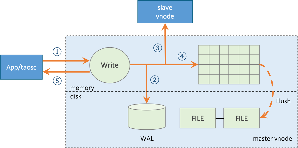
- Leader vnode receives the application data insertion request, verifies, and moves to next step;
- If the system configuration parameter
“walLevel”is greater than 0, vnode will write the original request packet into database log file WAL. If walLevel is set to 2 and fsync is set to 0, TDengine will make WAL data written immediately to ensure that even system goes down, all data can be recovered from database log file; - If there are multiple replicas, vnode will forward data packet to follower vnodes in the same virtual node group, and the forwarded packet has a version number with data;
- Write into memory and add the record to “skip list”;
- Leader vnode returns a confirmation message to the application, indicating a successful write.
- If any of Step 2, 3 or 4 fails, the error will directly return to the application.
Follower vnode Writing Process
For a follower vnode, the write process as follows:
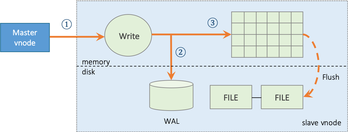
- Follower vnode receives a data insertion request forwarded by Leader vnode;
- If the system configuration parameter
“walLevel”is greater than 0, vnode will write the original request packet into database log file WAL. If walLevel is set to 2 and fsync is set to 0, TDengine will make WAL data written immediately to ensure that even system goes down, all data can be recovered from database log file; - Write into memory and add the record to “skip list”.
Compared with Leader vnode, follower vnode has no forwarding or reply confirmation step, means two steps less. But writing into memory and WAL is exactly the same.
Remote Disaster Recovery and IDC (Internet Data Center) Migration
As discussed above, TDengine writes using Leader and Follower processes. TDengine adopts asynchronous replication for data synchronization. This method can greatly improve write performance, with no obvious impact from network delay. By configuring IDC and rack number for each physical node, it can be ensured that for a virtual node group, virtual nodes are composed of physical nodes from different IDC and different racks, thus implementing remote disaster recovery without other tools.
On the other hand, TDengine supports dynamic modification of the replica number. Once the number of replicas increases, the newly added virtual nodes will immediately enter the data synchronization process. After synchronization is complete, added virtual nodes can provide services. In the synchronization process, leader and other synchronized virtual nodes keep serving. With this feature, TDengine can provide IDC migration without service interruption. It is only necessary to add new physical nodes to the existing IDC cluster, and then remove old physical nodes after the data synchronization is completed.
However, the asynchronous replication has a very low probability scenario where data may be lost. The specific scenario is as follows:
- Leader vnode has finished its 5-step operations, confirmed the success of writing to APP, and then goes down;
- Follower vnode receives the write request, then processing fails before writing to the log in Step 2;
- Follower vnode will become the new leader, thus losing one record.
In theory, for asynchronous replication, there is no guarantee to prevent data loss. However, this is an extremely low probability scenario as described above.
Note: Remote disaster recovery and no-downtime IDC migration are only supported by Enterprise Edition. Hint: This function is not available yet
Leader/follower Selection
Vnode maintains a version number. When memory data is persisted, the version number will also be persisted. For each data update operation, whether it is time-series data or metadata, this version number will be increased by one.
When a vnode starts, the roles (leader, follower) are uncertain, and the data is in an unsynchronized state. It’s necessary to establish TCP connections with other nodes in the virtual node group and exchange status, including version and its own roles. Through the exchange, the system implements a leader-selection process. The rules are as follows:
- If there’s only one replica, it’s always leader
- When all replicas are online, the one with latest version is leader
- Over half of online nodes are virtual nodes, and some virtual node is follower, it will automatically become leader
- For 2 and 3, if multiple virtual nodes meet the requirement, the first vnode in virtual node group list will be selected as leader.
Synchronous Replication
For scenarios with strong data consistency requirements, asynchronous data replication is not applicable, because there is a small probability of data loss. So, TDengine provides a synchronous replication mechanism for users. When creating a database, in addition to specifying the number of replicas, user also needs to specify a new parameter “quorum”. If quorum is greater than one, it means that every time the Leader forwards a message to the replica, it needs to wait for “quorum-1” reply confirms before informing the application that data has been successfully written in follower. If “quorum-1” reply confirms are not received within a certain period of time, the leader vnode will return an error to the application.
With synchronous replication, performance of system will decrease and latency will increase. Because metadata needs strong consistency, the default for data synchronization between mnodes is synchronous replication.
Caching and Persistence
Caching
TDengine adopts a time-driven cache management strategy (First-In-First-Out, FIFO), also known as a Write-driven Cache Management Mechanism. This strategy is different from the read-driven data caching mode (Least-Recent-Used, LRU), which directly puts the most recently written data in the system buffer. When the buffer reaches a threshold, the earliest data are written to disk in batches. Generally speaking, for the use of IoT data, users are most concerned about the most recently generated data, that is, the current status. TDengine takes full advantage of this feature to put the most recently arrived (current state) data in the buffer.
TDengine provides millisecond-level data collecting capability to users through query functions. Putting the recently arrived data directly in the buffer can respond to users' analysis query for the latest piece or batch of data more quickly, and provide faster database query response capability as a whole. In this sense, TDengine can be used as a data cache by setting appropriate configuration parameters without deploying Redis or other additional cache systems. This can effectively simplify the system architecture and reduce operational costs. It should be noted that after TDengine is restarted, the buffer of the system will be emptied, the previously cached data will be written to disk in batches, and the previously cached data will not be reloaded into the buffer. In this sense, TDengine's cache differs from proprietary key-value cache systems.
Each vnode has its own independent memory, and it is composed of multiple memory blocks of fixed size, and different vnodes are completely isolated. When writing data, similar to the writing of logs, data is sequentially added to memory, but each vnode maintains its own skip list for quick search. When more than one third of the memory block are used, the disk writing operation will start, and the subsequent writing operation is carried out in a new memory block. By this design, one third of the memory blocks in a vnode keep the latest data, so as to achieve the purpose of caching and quick search. The number of memory blocks of a vnode is determined by the configuration parameter “blocks”, and the size of memory blocks is determined by the configuration parameter “cache”.
Persistent Storage
TDengine uses a data-driven method to write the data from buffer into hard disk for persistent storage. When the cached data in vnode reaches a certain volume, TDengine will pull up the disk-writing thread to write the cached data into persistent storage so that subsequent data writing is not blocked. TDengine will open a new database log file when the data is written, and delete the old database log file after successfull persistence, to avoid unlimited log growth.
To make full use of the characteristics of time-series data, TDengine splits the data stored in persistent storage by a vnode into multiple files, each file only saves data for a fixed number of days, which is determined by the system configuration parameter “days”. Thus for given start and end dates of a query, you can locate the data files to open immediately without any index. This greatly speeds up read operations.
For time-series data, there is generally a retention policy, which is determined by the system configuration parameter “keep”. Data files exceeding this set number of days will be automatically deleted by the system to free up storage space.
Given “days” and “keep” parameters, the total number of data files in a vnode is: keep/days. The total number of data files should not be too large or too small. 10 to 100 is appropriate. Based on this principle, reasonable days can be set. In the current version, parameter “keep” can be modified, but parameter “days” cannot be modified once it is set.
In each data file, the data of a table is stored in blocks. A table can have one or more data file blocks. In a file block, data is stored in columns, occupying a continuous storage space, thus greatly improving the reading speed. The size of file block is determined by the system parameter “maxRows” (the maximum number of records per block), and the default value is 4096. This value should not be too large or too small. If it is too large, data location for queries will take a longer tim. If it is too small, the index of data block is too large, and the compression efficiency will be low with slower reading speed.
Each data file (with a .data postfix) has a corresponding index file (with a .head postfix). The index file has summary information of a data block for each table, recording the offset of each data block in the data file, start and end time of data and other information which allows the system to locate the data to be found very quickly. Each data file also has a corresponding last file (with a .last postfix), which is designed to prevent data block fragmentation when written in disk. If the number of written records from a table does not reach the system configuration parameter “minRows” (minimum number of records per block), it will be stored in the last file first. At the next write operation to the disk, the newly written records will be merged with the records in last file and then written into data file.
When data is written to disk, the system decideswhether to compress the data based on the system configuration parameter “comp”. TDengine provides three compression options: no compression, one-stage compression and two-stage compression, corresponding to comp values of 0, 1 and 2 respectively. One-stage compression is carried out according to the type of data. Compression algorithms include delta-delta coding, simple 8B method, zig-zag coding, LZ4 and other algorithms. Two-stage compression is based on one-stage compression and compressed by general compression algorithm, which has higher compression ratio.
Tiered Storage
By default, TDengine saves all data in /var/lib/taos directory, and the data files of each vnode are saved in a different directory under this directory. In order to expand the storage space, minimize the bottleneck of file reading and improve the data throughput rate, TDengine can configure the system parameter “dataDir” to allow multiple mounted hard disks to be used by system at the same time. In addition, TDengine also provides the function of tiered data storage, i.e. storage on different storage media according to the time stamps of data files. For example, the latest data is stored on SSD, the data older than a week is stored on local hard disk, and data older than four weeks is stored on network storage device. This reduces storage costs and ensures efficient data access. The movement of data on different storage media is automatically done by the system and is completely transparent to applications. Tiered storage of data is also configured through the system parameter “dataDir”.
dataDir format is as follows:
dataDir data_path [tier_level]
Where data_path is the folder path of mount point and tier_level is the media storage-tier. The higher the media storage-tier, means the older the data file. Multiple hard disks can be mounted at the same storage-tier, and data files on the same storage-tier are distributed on all hard disks within the tier. TDengine supports up to 3 tiers of storage, so tier_level values are 0, 1, and 2. When configuring dataDir, there must be only one mount path without specifying tier_level, which is called special mount disk (path). The mount path defaults to level 0 storage media and contains special file links, which cannot be removed, otherwise it will have a devastating impact on the written data.
Suppose there is a physical node with six mountable hard disks/mnt/disk1,/mnt/disk2, …,/mnt/disk6, where disk1 and disk2 need to be designated as level 0 storage media, disk3 and disk4 are level 1 storage media, and disk5 and disk6 are level 2 storage media. Disk1 is a special mount disk, you can configure it in/etc/taos/taos.cfg as follows:
dataDir /mnt/disk1/taos
dataDir /mnt/disk2/taos 0
dataDir /mnt/disk3/taos 1
dataDir /mnt/disk4/taos 1
dataDir /mnt/disk5/taos 2
dataDir /mnt/disk6/taos 2
Mounted disks can also be a non-local network disk, as long as the system can access it.
Note: Tiered Storage is only supported in Enterprise Edition
Data Query
TDengine provides a variety of query processing functions for tables and STables. In addition to common aggregation queries, TDengine also provides window queries and statistical aggregation functions for time-series data. Query processing in TDengine needs the collaboration of client, vnode and mnode.
Single Table Query
The parsing and verification of SQL statements are completed on the client side. SQL statements are parsed and generate an Abstract Syntax Tree (AST), which is then checksummed. Then metadata information (table metadata) for the table specified is requested in the query from management node (mnode).
According to the End Point information in metadata information, the query request is serialized and sent to the data node (dnode) where the table is located. After receiving the query, the dnode identifies the virtual node (vnode) pointed to and forwards the message to the query execution queue of the vnode. The query execution thread of vnode establishes the basic query execution environment, immediately returns the query request and starts executing the query at the same time.
When client obtains query result, the worker thread in query execution queue of dnode will wait for the execution of vnode execution thread to complete before returning the query result to the requesting client.
Aggregation by Time Axis, Downsampling, Interpolation
Time-series data is different from ordinary data in that each record has a timestamp. So aggregating data by timestamps on the time axis is an important and distinct feature of time-series databases which is different from that of common databases. It is similar to the window query of stream computing engines.
The keyword interval is introduced into TDengine to split fixed length time windows on the time axis. The data is aggregated based on time windows, and the data within time window ranges is aggregated as needed. For example:
select count(*) from d1001 interval(1h);
For the data collected by device D1001, the number of records stored per hour is returned by a 1-hour time window.
In application scenarios where query results need to be obtained continuously, if there is data missing in a given time interval, the data results in this interval will also be lost. TDengine provides a strategy to interpolate the results of timeline aggregation calculation. The results of time axis aggregation can be interpolated by using keyword Fill. For example:
select count(*) from d1001 interval(1h) fill(prev);
For the data collected by device D1001, the number of records per hour is counted. If there is no data in a certain hour, statistical data of the previous hour is returned. TDengine provides forward interpolation (prev), linear interpolation (linear), NULL value populating (NULL), and specific value populating (value).
Multi-table Aggregation Query
TDengine creates a separate table for each data collection point, but in practical applications, it is often necessary to aggregate data from different data collection points. In order to perform aggregation operations efficiently, TDengine introduces the concept of STable (super table). STable is used to represent a specific type of data collection point. It is a table set containing multiple tables. The schema of each table in the set is the same, but each table has its own static tag. There can be multiple tags which can be added, deleted and modified at any time. Applications can aggregate or statistically operate on all or a subset of tables under a STABLE by specifying tag filters. This greatly simplifies the development of applications. The process is shown in the following figure:
- Application sends a query condition to system;
- TAOSC sends the STable name to Meta Node(management node);
- Management node sends the vnode list owned by the STable back to TAOSC;
- TAOSC sends the computing request together with tag filters to multiple data nodes corresponding to these vnodes;
- Each vnode first finds the set of tables within its own node that meet the tag filters from memory, then scans the stored time-series data, completes corresponding aggregation calculations, and returns result to TAOSC;
- TAOSC finally aggregates the results returned by multiple data nodes and send them back to application.
Since TDengine stores tag data and time-series data separately in vnode, by filtering tag data in memory, the set of tables that need to participate in aggregation operation is first found, which reduces the volume of data to be scanned and improves aggregation speed. At the same time, because the data is distributed in multiple vnodes/dnodes, the aggregation operation is carried out concurrently in multiple vnodes, which further improves the aggregation speed. Aggregation functions for ordinary tables and most operations are applicable to STables. The syntax is exactly the same. Please see TAOS SQL for details.
Precomputation
In order to effectively improve the performance of query processing, based-on the unchangeable feature of IoT data, statistical information of data stored in data block is recorded in the head of data block, including max value, min value, and sum. We call it a precomputing unit. If the query processing involves all the data of a whole data block, the pre-calculated results are directly used, and no need to read the data block contents at all. Since the amount of pre-calculated data is much smaller than the actual size of data block stored on disk, for query processing with disk IO as bottleneck, the use of pre-calculated results can greatly reduce the pressure of reading IO and accelerate the query process. The precomputation mechanism is similar to the BRIN (Block Range Index) of PostgreSQL.